Project Insights
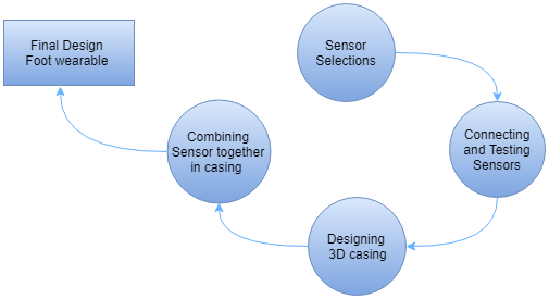
The design process follows the road shown in the following flowchart. As the first step is to decide the sensor which can be incorporated in building the foot wearable platform for snow and ground charactertization. Afterwards, the individual sensor connection and testing is performed. The functionality and purpose of different sensors is explained in detail in later sections. Following, the step of designing of 3D model casing for the purpose of integrating all the components together. The final stage encompasses the combining of all the products of previous phase to form a final design of foot wearable platform.
System Implementation
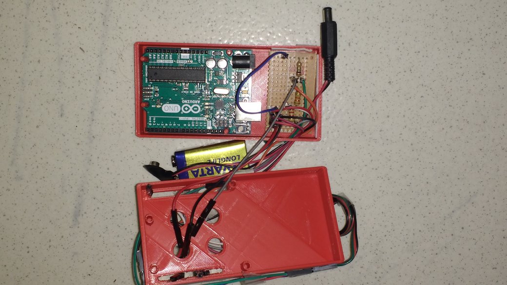
The final product is consists of sensors and arduino board enclosed in 3d casing model, for the purpose of attaching the sensor platform to the foot as illustrated in the figure (4) below. HC -05 Bluetooth and DHT 22 temperature sensors are placed inside the box presents at the top as shown in the figure (5) below, whereas the flexi force sensor is placed inside the shoe.

As a working principle of the system, DHT22 collects the information of temperature and humidity from the external surroundings and transmits it as a digital signal via MaxDetect 1-wire to the arduino board. The arduino receive 40 bits in the form of digital signal, in which the first 16 data bits represents Relative Humidity, next 16 data bits represents the Temperature and last 8 bits are check sum bits. Whereas, the change in analogue output voltage is occurred when the force is exerted on the sensing area of FSR. The voltage is calculated as: Vo = Vs * R/(R+FSR)